

oomph
Today’s entry is about a wider group of effects: the boosters. What is “boosting”? Well, quite simple: amplification of the signal. Ok, but doesn’t our amp do that? Yes, indeed, but the signal coming from your guitar is amplified already in your amp in several steps until it arrives to the speaker. If you add some effects to the signal chain, then you introduce further amplification stages with these. Yes, even with modulation effects. Well, then what exactly is a booster? Actuallay anythign that amplifies your signal, question is only what else you want to do with the signal besides amplifying it. A phaser or a tremolo might amplify your signal, but if you don’t need the modulation that these effects give, then these are not the best tools for you. Or an overdrive might also amplify your signal, but also distorts it which might not what you need again. In most cases people expect clean boosting from a booster device, that is only increasing the level of the signal without any further alteration – this is called “clean boosting”. You can achieve this with quite a few effect types: an EQ, a compressor or even an overdrive with the gain/drive turned all the way down and the level/volume as high as needed (however in most cases this is only “almost clean boosting”) can be useful, but there are devices designed for exactly this puropse, the boosters. An important thing is the frequency response. In an ideal case the amplification is independent from the frequency, so all frequencies are amplified the same amount. A guitarist would say the effect does not “color” the sound. Now in real life this does not happen, and that is the reason why guitarists are picky about such simple devices like boosters too.
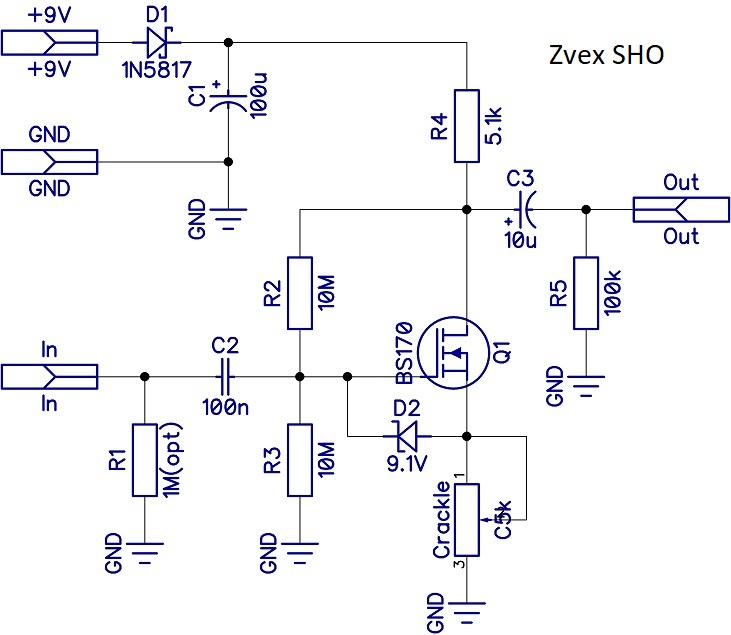
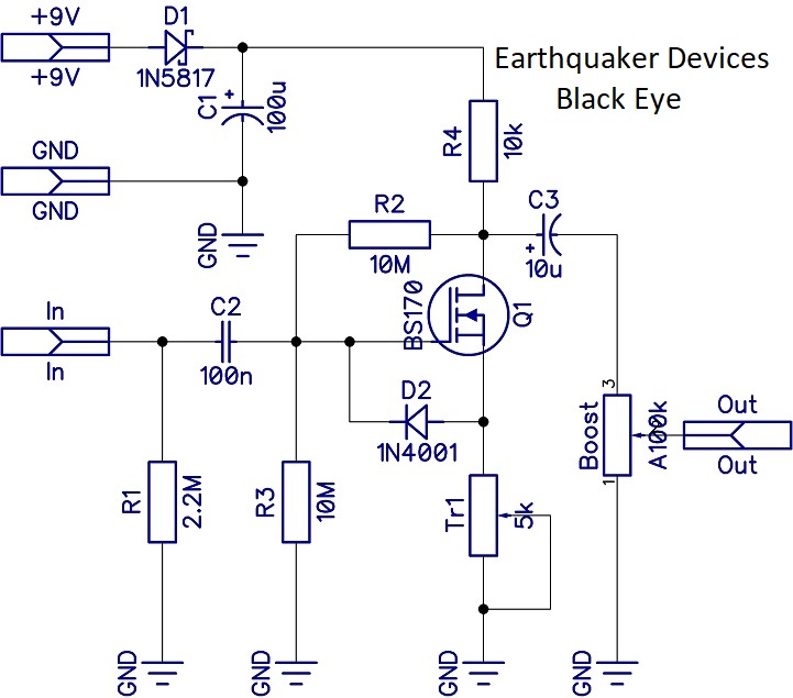
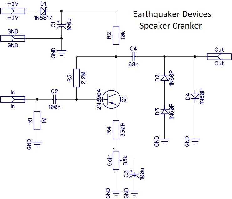
In this entry I’m trying to show you a project that makes it possible to build four types of boosters on the same board. With some modifications of the parts you can even build an overdrive/distortion type of effect. Of course there are way more booster types out there than these four, but these are the basics. They are even basic building plocks in many other effects, e.g.: the Big Muff basically consists of four similar booster stages. In our project there is a discrete transistor stage in use. There are of course boosters made with opamps as well (e.g.: the Demeter Fat Control that we already mentioned in the Piece’O’Cake project), I promise in the future at some point I will write about those too. Within this project you will be able to build the following boosters: Electro Harmonix LPB1, Zvex SHO, Earthquaker Devices Black Eye and Speaker Cranker. The latter one is already a bit of an overdrive too at higher gain settings.
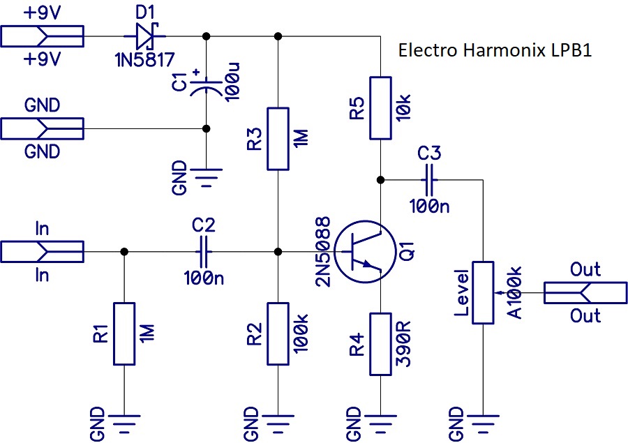
If you compare the above schematics you will see the similarities between them. It is not a coincidence: this is the simplest way to make a transistor amplify your signal (without thinking twice about the type of transistor). This basic circuit is called the common emitter circuit – or common source in case of FETs. Here I will not dig deep into the physics and mathematics of this circuit, others can do that much better. The basic operation is following: as the signal changes so does the current on the base of the transistor. This current controls how much current the transistor lets flow between the emitter and collector. Since this emitter-collector current comes from the power supply, you can increase the level of the original signel from a few millivolts to a few volts (in an ideal case with 9V of power supply and center biased transistor the output level can be +/-4.5V).
 Summary:
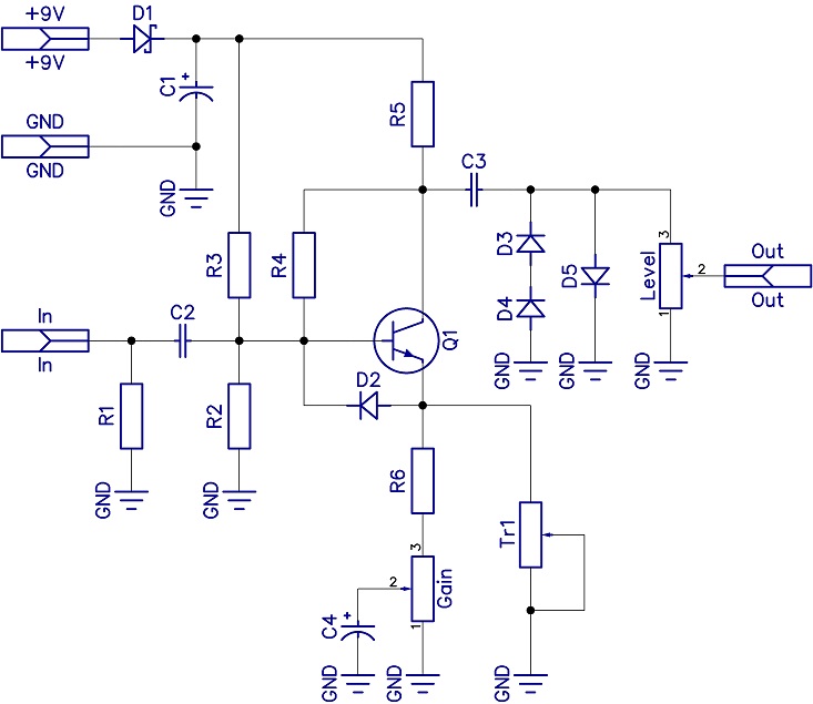
The above circuit shows the combination of all four schematics. I have handled the circuit signs of the parts loosely, for example the transistor is marked with the sign of the bipolar junction transistors, even though we know that the SHO and the Black eye both use a MOSFET in this position. I have not marked the values of each part, this is summarized in tables in the build docu that – as usual – can be found under the Projects menu. I highly recommend esperimenting with the parts, here some guidelines for the role of each part:
– D1: Polarity protection. It has a low voltage drop, but that is not enough to consider large changes in tone with leaving it off.
– C1: Filters the power supply. These days guitarists usually use stabilized and filtered power supplies, so in an ideal case it has noreal effect, but it does not harm either.
– R1: If you build your effects true bypass (most of us do that), then this pull-down resistor prevents the popping when the effect is switched on. Basically it prevents the C2 input decoupling cap from charging, which then could discharge to your signal line when the effect is switched on.
– C2, C3: Input and output decoupling caps prevent DC to appear on the input or output. DC could harm your gear at the input and output. The larger these are the more bass they let through. Definitely something to experiment with.
– R2, R3: These set the bias of the transistor – where they are present.
– R4: Feedback of the signal – where it is present.
– R5, R6, C4, Gain és Tr1: R5 is the collector resistor, R6, C4, Gain and Tr1 together give the emitter resistance. A rough estimation for the gain is the ratio of the collector and emitter resistances. The collector resistor is a fixed value (R5), but at the emitter there is often a variable resistance (the Gain pot or the Tr1 in some of the designs we list here). With that the stage’s gain can be changed. In a clean booster this does not have much effect, as we don’t really need all that much gain anyways. But this can set the range in which the final Level pot is working. In the case of an overdrive however this can change the level of distortion, see the Speaker Cranker. The C4 cap changes the frequency response of the stage. Below the cut-off frequency that is determined by its size the gain of teh signal drops off as those frequencies “see” gradually larger resistance at the emitter.
– D3, D4, D5: These are the clipping diodes for the Speaker Cranker only, these do the distortion of teh signal. You can check out the Electra Distortion circuit too, you can also build taht one based on this layout for example.
No Comments