
Fuzz-O-Tron
If I say “fuzz”, most of you will reply with “Fuzz Face” when playing an association game. In today’s post I’m not going to write about this iconic pedal, but about one of its close relatives: the Zvex Mastotron. The Fuzz Face circuit is a simple one and has inspired many builders. You should not think of any dramatic changes, but many have tried to improve the original effect with adding more controls and thus giving more tonal options. There are quite useful and not that useful mods out there. The Zvex Mastotron belongs to the first category. All its pots are useful and work in a useful range, there are no “dead spots”. All the available tones are good: from lighter blues-like fuzz all the way up to stoner/doom madness. If you want some more weird sounds you can achieve some velcro-like, slightly gated fuzz tones by turning the PW and Relax/Push pots. If you want only one fuzz this might very well be the one. Of course it can’t cover all the fuzz tones in the world – only a Big Muff sounds like a Big Muff – but the wide tonal variety makes this pedal a really versatile one.
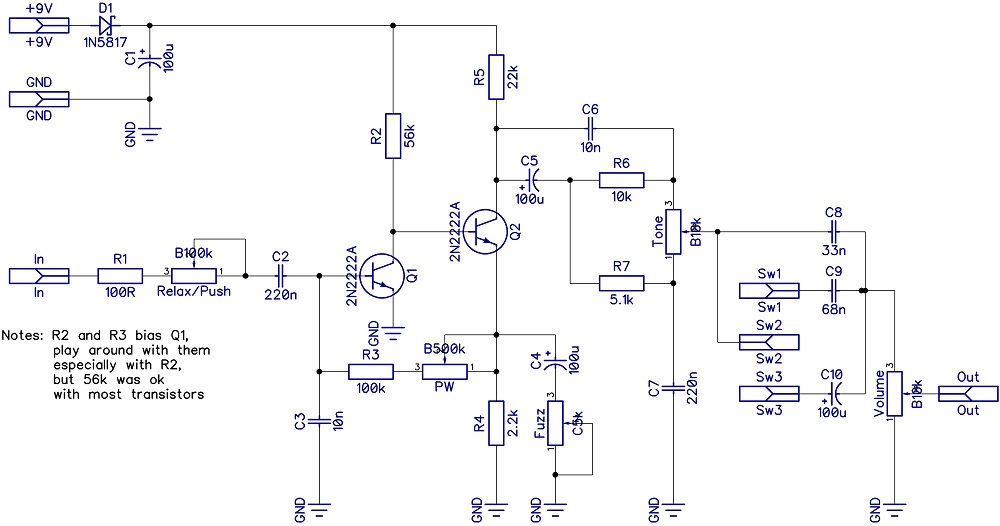 From the circuit it is clear that the effect is built on the bases of the good old Fuzz Face, or to be more precise on its modern NPN transistor incarnation. R.G. Keen has a very good writing about the Fuzz Face’s technology on his website, I really recommend reading it if you are interested in the technical details (actually his complete “The technology of…” series is very good). The mods to the original are the following:
– The Relax/Push pot that can attenuate the incoming signal.
– The PW pot that controls the feedback between the two transistors.
– The complete Tone section, which is missing from the original Fuzz Face.
– The switch at the end which changes the value of the final decoupling capacitor, thus controls the bass content of the effect.
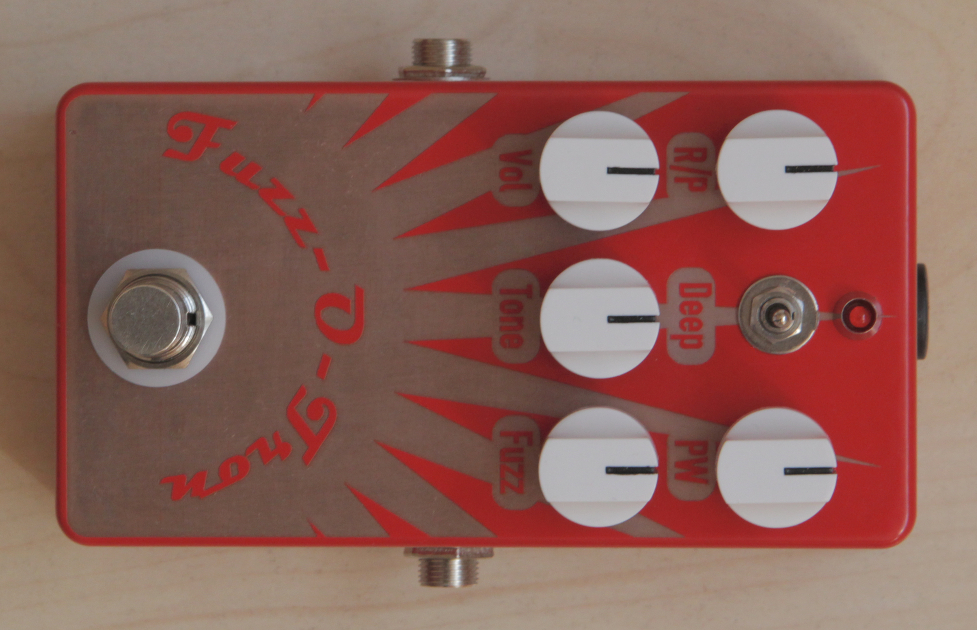
The circuit itself is really small, but because of the high number of controls it only fits into a 125B box. You might try to fit it into a 1590B as well if you connect the pots with wires and use the smaller 9mm pots.
It is important to bias the Q1 transistor correctly: you can do this with the 56k R2 resistor. The original value seems to be ok for most transistor types I tried, but substitute it with a pot or trimmer if you want to experiment. In that case however don’t forget to add a fixed resistor for a minimum value (say 1k) to avoid burning your Q1 transistor. You might also consider to put this pot on the outside as an additional tonal option, however I did not find it particularly useful.
You can find the build docu under the Projects menu.
Aaron
2022.08.22. at 21:03So is the switch basically a spdt with two separate caps tied to either pole?
fizikus
2022.08.23. at 06:29Exactly, I just marked them as simple pads for the PCB, as usually I don’t use on-board switches (the drilling template is easier this way).
AB
2022.09.26. at 17:59Is your C5k pot LOG or Rev-Log? I know the C value can vary based on continent
fizikus
2022.09.26. at 18:51Rev-Log. As much as I know A and B are used sometimes the other way around (I think in Japan B stands for logarithmic and A for linear), but C always designates reverse logarithmic taper.