
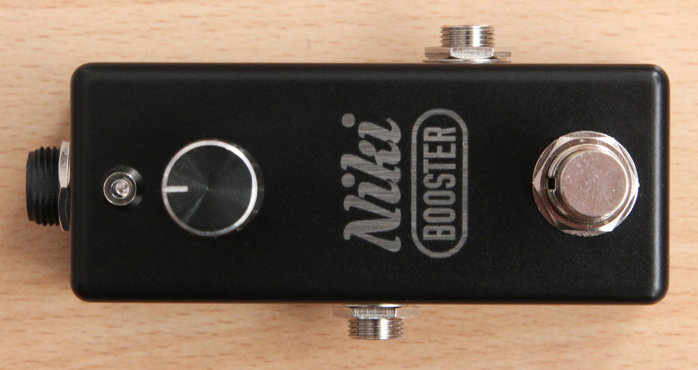
Epic Booster
So far there has not been much talk about the booster effects on this page. This is a very basic effect type. What do they do, what are their uses? Basically they are simple amplifiers: they simply amplify the signal they get on their input. This has several uses: on one hand we can push our amp’s input or our overdrive effects with a higher signal level and thus get a higher distortion. On the other hand we can either put them in the effect loop of the amp or if we use the clean channel of a high headroom amp then directly at the input of the amp and increase the volume of our sound. This can help making our solos to jump out from the mix. This entry is about Xotic’s EP Booster. In the old times many guitarists used the pre-amp of the EchoPlex – a tape delay. They often used it all the time on, without blending in the echo/delay effect. The EP Booster is the modern, FET-based realization of this old effect’s pre-amp. There is the boost pot on the outside and there are two DIP switches on the PCB which control the boost of different frequency ranges. Honestly I did not find any large effect of these two switches which may very well be the reason for not having them on the outside as normal switches. The effect boosts the signal already at turned down boost pot considerably, maybe this is why people often like to use it as an “always on” effect.
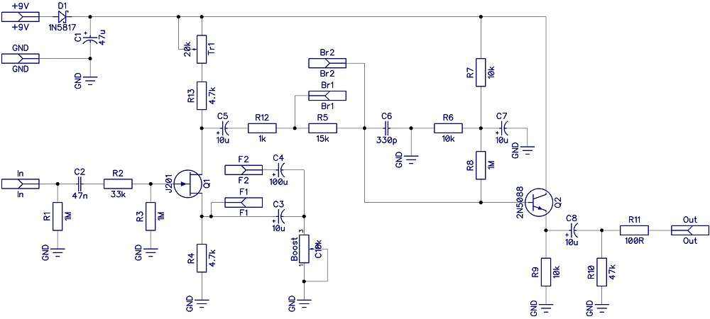 It is not a complicated design, a simple JFET-based common source stage does the boosting itself and it is followed by a BJT-based emitter-follower buffer stage. The amount of boost can be controlled by decreasing the source resistor. In the original the drain resistor is 8.2kOhm, I have changed this to a 4.7kOhm resistor with a 20kOhm trimmer in series. Turning the trimmer all the way down the gain is about 1, however the whole boost range also goes lower a bit, so the maximum boost pot setting is not giving as much of a gain (but still high enough). Turning the trimmer up the complete boost range is shifted upwards. F1/F2 and Br1/Br2 are the connectors for the two DIP switches in the original. In my version for saving space on the PCB I have used simple jumpers instead. The original uses the good ole’ J201 FET transistors, however since JFETs are getting really scarce these days you can try any JFETs here with the same pinout. I have used J202s with great success but 2N5457 and 2N5458 might be good as well. The drain trimmer helps to shift the boost pot’s range to the desired range with any of these JFETs.
The build docu can be found under the Projects menu.
No Comments