
The Depth
Today we have another “essential” effect: the delay. Sometimes delay is also called echo. The basic operation is following: after the input the signal is split. In one direction it goes unaltered to the output mixer. In the other direction it goes through a circuit that delays the signal and after the predefined delay time it sends the copy to the output mixer and repeats this as predefined too. The delay time and the number of repeats can usually be set by pots, these are called “Delay” or “Time” and “Repeat” or “Feedback”. Often we have a pot called “Mix” too that sets the proportion of the clean and effected signals.
The delay circuit can be analog or digital. The analog solutions usually use the so called BBD (Bucket Brigade Delay) chips. These are essentially long chains of caps, where discharging one cap charges the next one in the chain and so the signal travels through the chain like the water is spilled from one bucket to another used in the past by fireman brigades (hence the name “Bucket Brigade”). Today these are very popular due to their warm analog sound. I would not argue with their qualities (anyone who has already heard the EHX Memory Man knows what I’m talking about), but the solution has its limits: compared to the digital solutions the analog ones can pick up/generate quite some more noise especially in case of longer delay times. Also compared to the digital designs shorter delay times are possible plus the BBD chips are rare and expensive today – just look up MN3005 or MN3308 on ebay and you will be surprised by the price compared to the popular PT2399 digital chip. And usually an analog delay needs at least two of such BBD chips… I think that though the analog designs are nice and undeniable have their qualities, today’s popularity is rather due to the “vintage” attribute associated with them.
The digital circuits are usually associated with sterile and bright sounds, but in practice one can achieve really nice warm sounds with these too. Logically at least it is more simple to achieve delay with digital techniques: the signal is first converted to digital (A/D conversion), then put in a digital memory where it can stay theoretically as long as desired. Then it can be read out, and converted back to analog (D/A conversion). Of course the size and type of the memory in use has its limits too, but in practice much longer delay times can be achieved with less noise than with the analog designs. In the DIY world the PT2399 chip is very popular. Originally it has been developed for the echo modules of karaoke devices, but already the example circuit in the datasheet is usable for guitars. In essence this example circuit is used by all PT2399-based designs starting from home builders to boutique builders. The difference is the input buffer/amp and the mixing amp at the end. This is usually achieved with an additional opamp. The big companies like Boss or Ibanez use their own chips.
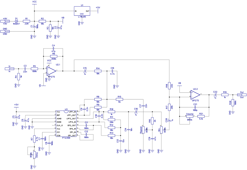
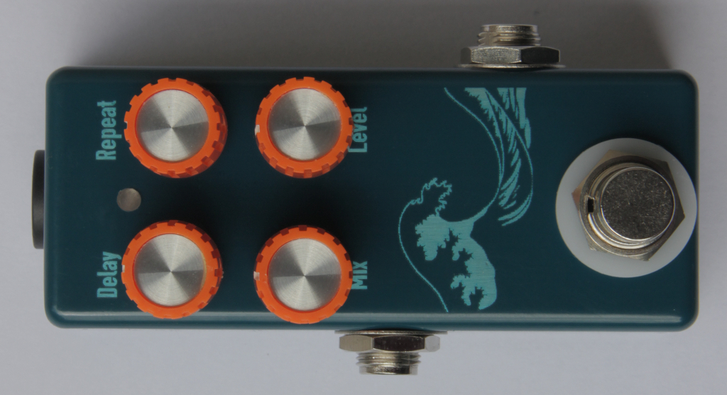
This blog entry is about Mad Professor’s Deep Blue Delay. Comparing the schematic with the example circuit in the datasheet of PT2399 we can see that indeed the difference is the opamp used for splitting and mixing the dry and effected signal paths. The original has the somewhat pricey OP275 opamp, but in my experience any simple dual opamp can be used – I have used TL072 with success. The only little change I have made is the “Volume” pot. Instead of that and R21 the original has only one 12k resistor in the feedback loop of the mixer that provides a fixed gain of that stage. With my solution you can set the overall volume of the effect too. Sometimes I have experienced that C4 and C21 can suck too much of the highs. The purpse of these is to prevent oscillation of the opamp stages. It makes sense to socket these and try as low values as possible to retain as much of the highs as possible. If you are lucky you can omit them altogether. The delay time is set by the “Delay” pot and R7. The minimum delay time is defined by R7 and the maximum is defined by the maximum value of the pot plus the R7 resistor. With the values on the schematic about 600ms delay time can be achieved. If you want more you can play with these values, but the higher you get with the delay times the more digital noise will be present – this is how the PT2399 works unfortunately. Since we are talking about the flaws of the PT2399: you have to be aware that these are not the best chips in the world. Either QC is poor or the thresholds are too low, but there are big variations between the individual chips. I would strongly suggest to socket the chip and to try several ones. You might find one to have less noise than the other, so it makes sense to buy a few not only one when you plan to build any designs based on this chip. However if everything works out well with this effect I have to say it is a very nice DIY delay solution that easily can make its place in your pedalboard.
As usual the build docu build docu can be found under the Projects.
No Comments