
Little Prick
Yet antoher iconic piece from the imaginary Top 100 Guitar Pedals list: the Electro-Harmonix Big Muff Pi. Most guitarists try this too during their life. The characteristics are the high gain with solid, compressed, sometimes violin-like sound. Very popular among stoner and grunge musicians, but such classical rock guitarists like David Gilmour and Pete Townshend used it too. There is a very good webpage ot there on the internet where you can learn everything about the history of this pedal and its different incarnations: Kit Rae’s Big Muff Page.
 Today’s post is a bit about stealing something from everyone :) So instead of trying to analyse the circuit with my poor knowledge I rely on the professionals and let me refer to the Electrosmash page, where besides the Big Muff Pi analysis there are many other guitar effects analysed. As you can see the schematic does not contain values. The reason is that I wanted to create a PCB layout that can be used for many versions, not only a specific one. The values can be found in the build docu for several well known versions.
I would like to talk a bit more in depth about the tone stack though. This is a famous one and is also often referred to as the “BMP (Big Muff Pi) tone stack”. At its very basics it is a low-pass and a high-pass filter where the output of the both goes to a mix pot (the Tone pot). In the original BMP versions this tone stack provides a “scooped mid” frequency response. I don’t like it too much as it tends to get lost in the mix, especially if there are other guitars too. With varying the values in the tone stack one can of course get a nearly linear frequency response or a bit of mid boost as well. I like these options much more. In my builds I tend to add a switchable option to switch a second cap in paralel to the original C10 (4nF) with the values of 6.8nF (giving 10.8nF in total and resulting in a “flat” frequency response) or of 22nF (giving 26nF in total and resulting in a slight boost in the low mids).
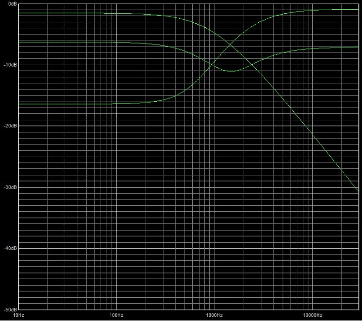
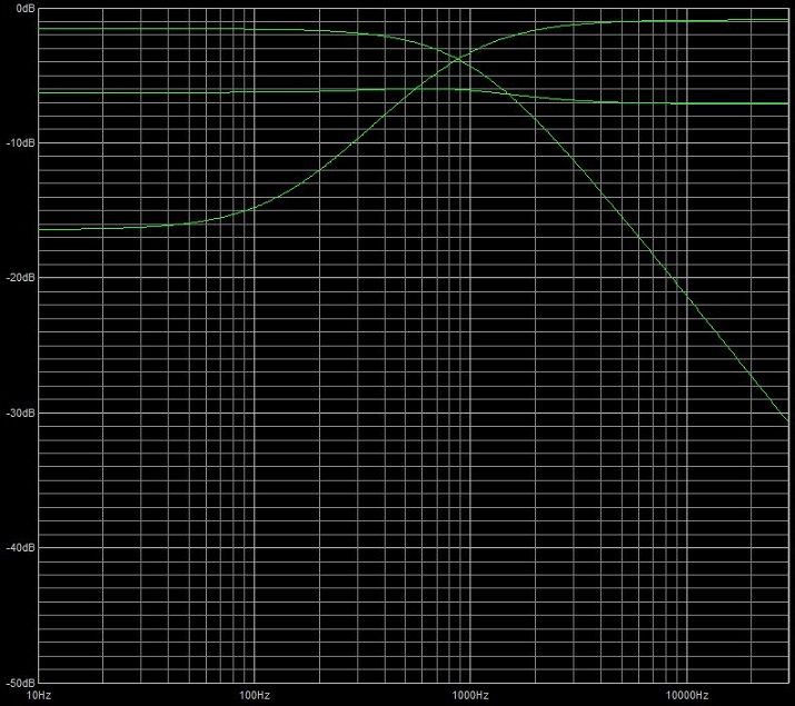
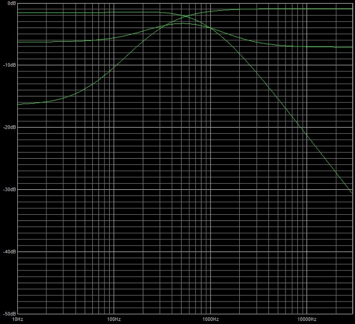
From these frequency responses it is also visible that by changing one of the filters (in this case the high-pass filter) one also changes the signal level pretty much. It is also worth mentioning that the BMP tonestack is known to suck quite a lot of the signal level, that’s the main reason for having the last transistor stage which compensates for this signal level drop.
There are two easy fields to mod a Big Muff: the clipping diodes and the transistors.
As usual I always encourage people to try as many clipping diode configurations as possible where these are used. I have tried quite a few Big Muff relatives, some used LEDs and some even FETs as clipping diodes. The change is not huge, though in general the Ge and Schottky diodes tend to result too much compression for my taste. LEDs give you a more open sound.
Changing the transistors gives you a bigger change in tone. For me the winner is the good ole’ 2N5088 or if I want a more saturated and compressed sound, then the MPSA18. For the Russian versions I prefer the lower hFE transistors.
You can find the build docu at the usual place, under the Projects menu.
No Comments